Flipper Box/IR Breakout Board
New Toys
5/20/2025
Towards the beginning of summer I bought an electronics starter kit to get some hands on experience with circuits and microcontroller use. For most of my tech career I've been
primarily focused on working with software so doing some hands on stuff with electronics was a nice change of pace. After putting together some basic projects, I started
to brainstorm ideas for a larger project to work on. Since I had fairly recently gotten a Flipper Zero, which has various remote communication capabilities, I thought that building
a device which could interface with all these communication methods would be a very interesting project.
Plans
5/27/2025
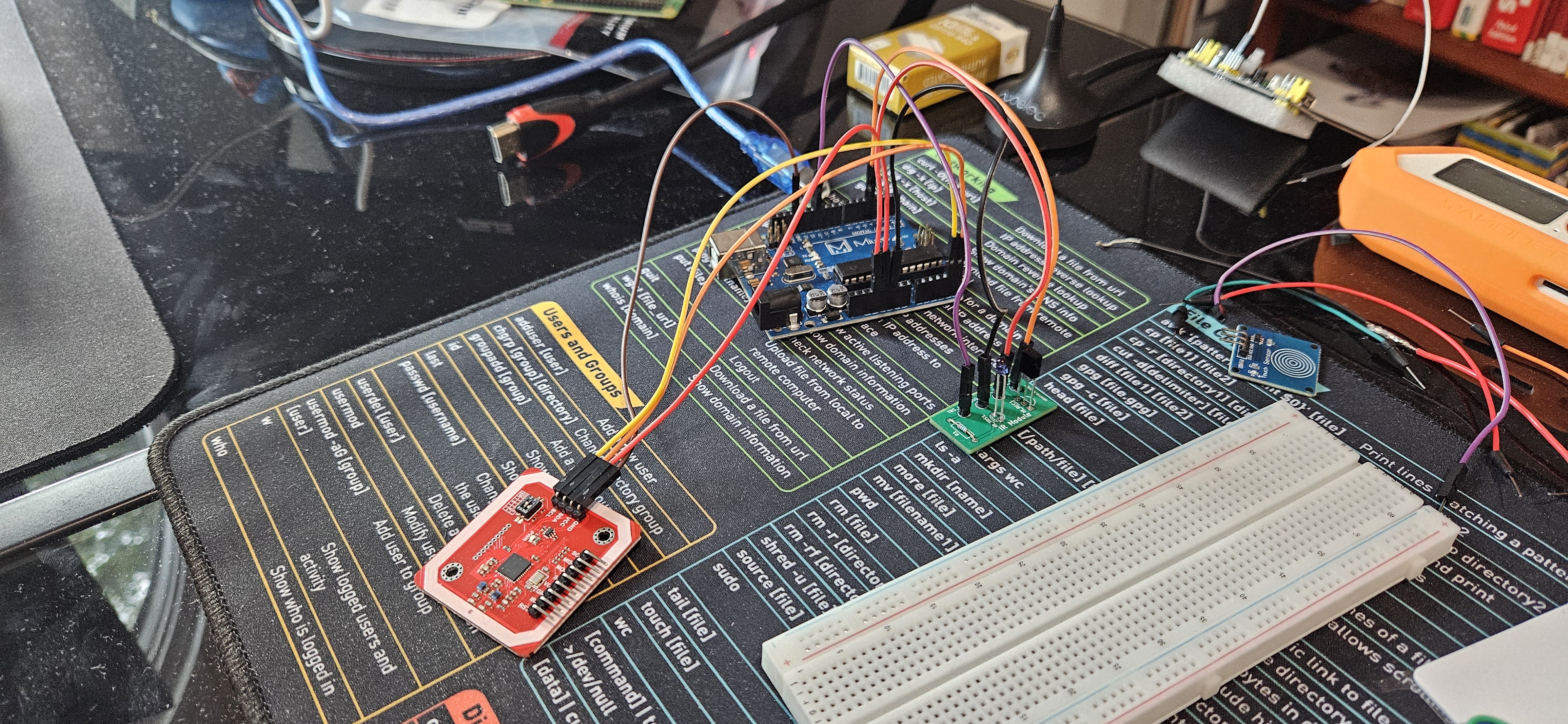
The Flipper Zero is capable of receiving and emulating a variety of over the air communication methods including subGHz radio, infrared, RFID, and NFC. What I wanted to do was construct a
device which would be able to receive these signals from the Flipper Zero, as well as transmit it back to either the Flipper or really to any other device with the right receiver. For this project
the central "brain" was going to be the microcontroller which came with the electronics starter kit. The microcontroller itself was really just an off brand Arduino, using the same ATmega328P
microcontroller chip, with the main difference being just the appearance of the circuit board around it. For NFC/RFID I decided to go with the PN532 NFC RFID Module from Elechouse
since it was fairly inexpensive and supported most of the things I would need for the project. For the subGHz radio functionality, I wasn't able to find a good development board so instead I ended up
using a SDR from Nooelec with the
caveat that it would only be able to receive subGHz radio. Finally, for the infrared part of my project, I decided to design my own PCB as I thought that it would be fairly simple to do for this component
and would expose me to some circuit design techniques/software.
Highlights
- Worked out how the different components for my "Flipper Box" device will be connected and used.
- Purchased necessary development modules.
- Started IR board design.
IR Board Design
6/4/2025
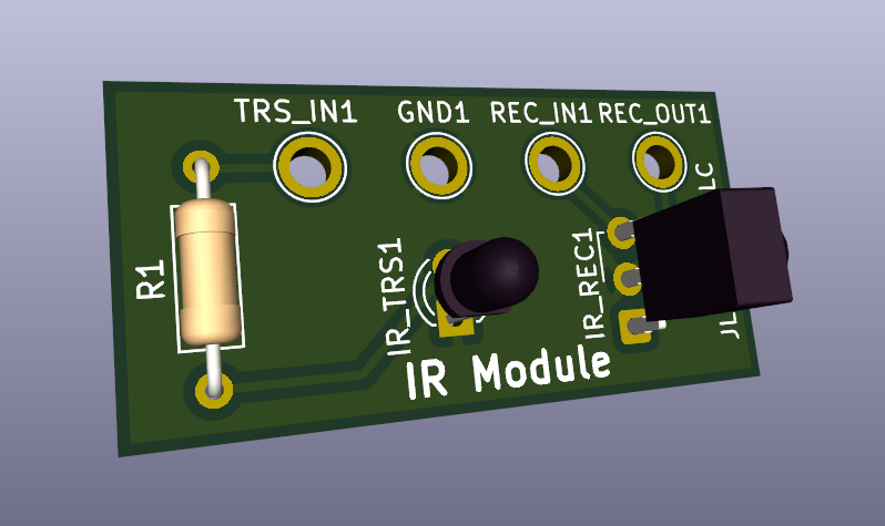
Once I had all the components purchased for my project, I started work on the infrared printed circuit board design. I decided to use KiCad for this since it's completely free and from experience much more
approachable compared to alternatives like Altium Designer. While the board itself is very basic, designing it did take a couple of days as I was also getting used to the design software at the same time.
In the process I learned about concepts specific to PCB design like nets, trace/board dimensions, and power/ground planes. After completing my design, I exported the gerber files and sent them off to JLCPCB
for manufacturing. I also bought the necessary components to solder onto the PCB's once they arrive.
Highlights
- Worked on and finished design for IR board.
- Bought the necessary electronic components to solder onto board.
Next Steps
6/20/2025
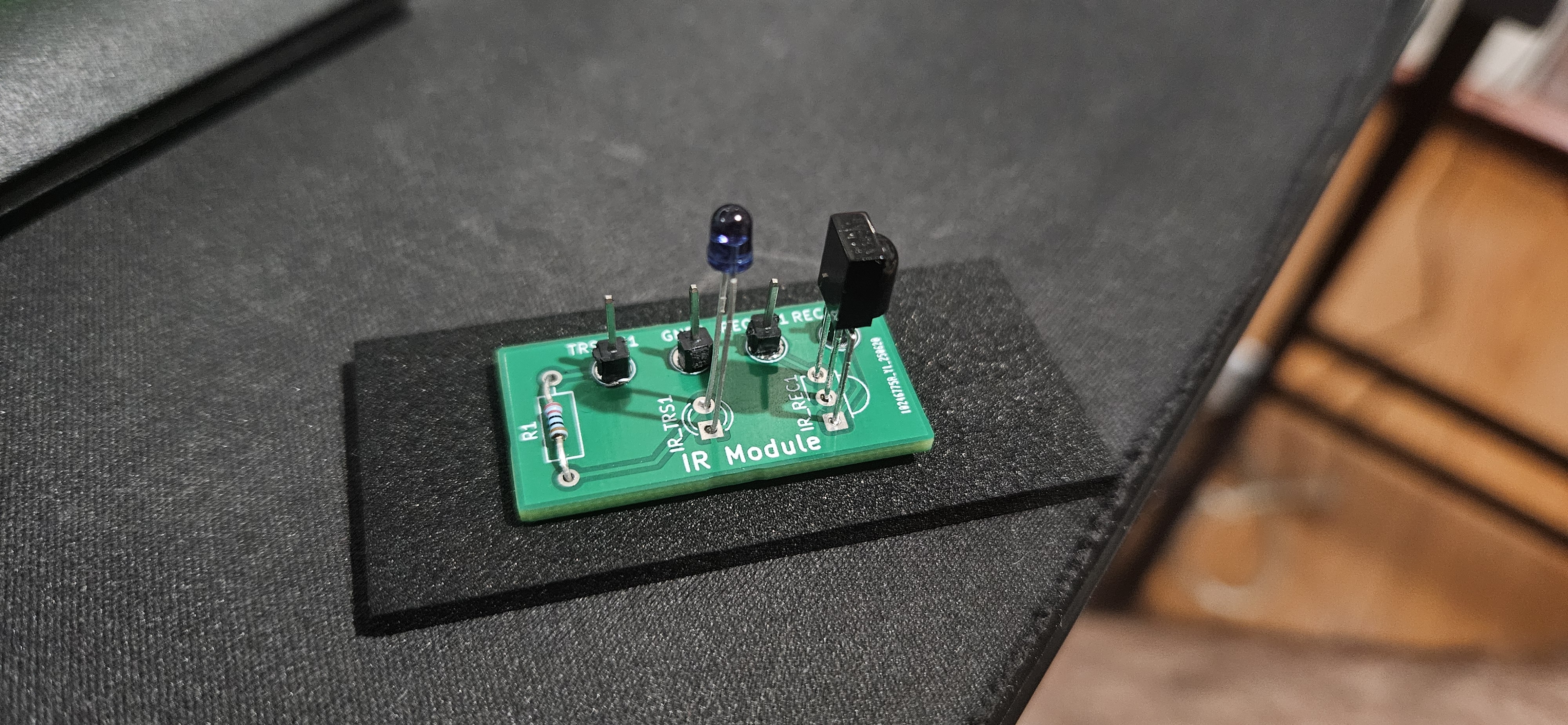
The PCB's have arrived and I have soldered on the necessary components onto one of the boards. It took a little while as some of the components were finicky and admittedly the boards design could have
been better as well. I have tested the board and it seems to be working correctly with the microcontroller. For the next step, I need to assemble the whole device, connect all the boards to the MCU,
and write some code to implement the desired functionality.